Добро пожаловать в VEO Bearings Europe!


2..-K-CA-W33
Категория:
Сферические роликовые подшипники
Общайтесь с нами сейчас для быстрого ответа.
Получите квалифицированную консультацию по продажам в течение 12 часов.
Ключевое слово:
2..-K-CA-W33
ДЕТАЛИ ПРОДУКТА
Technical characteristics
Spherical roller bearings are non separable do- uble row radial bearings.
Both rows of barrel shaped rollers rotate,in pa- rallel,within the spherical outer ring.This allows an excellent alignment compensation,caused by machining and mounting errors,between the shaft and housing.
Their boundary dimensions ara standardized by de DIN Standard 616 and DIN 635/parte2.
Spherical roller bearings are typical bearings for heavy machinery and mining.
They are suitable for applications with large ra- dial loads or where larger misalignments may occur.They are also able to support minor axial forces in both directions.
Due to their kinematic behaviours,spherical ro- ller bearings are only suitable for operating at low to medium speeds.
VEO spherical roller bearings are produced in open design as standard.
They are frequently used with tapered bores (ta- per 1:12)namely suffix K exceptfor series 240, 241,248 and 249 where the taper bore (1:30)is namely suffix K30,for ease of mounting.
The facility of mounting these bearing types using adapter and extraction sleeves enables mounting directly onto drawn or fine turned seats of shaft for applications where high running
accuracy is not necessary.
For some applications it remains necessary to mount tapered bore bearings directly onto a ta- pered seat of the shaft.
Standard design variants
VEO spherical roller bearings are produced in se- veral designs,depending on bearing series and size.The main differences are in the design of the inner ring and/or cages.
Cages
There are five different models of cages with different characteristics according to material and shape depending on the application where the bearing is in use.These designs are described
below:
CC.:two window-type steel cages,flange- less inner ring and guide ring centred on the inner ring
CA.:one piece solid brass cage,retaining flanges on the inner ring,centred on the inner ring
CAF.:as CA,but with a steel cage
MA.:two pieces solid brass cage,outer ring guided
MB.:twopiecessolid brass cage,inner ring guided
For the availability of Spherical roller bearings with other cages,please contact VEO
Spherical roller bearings for shaker screens
Bearings in these applications are subjected to very severe operating conditions.The shaking ac- tion of the screen subjects the bearings to very heavy loads including impact loads.Additional
loading on the bearing is created by the higher “g”forces generated by higher acceleration pre- sent in the application.Heavy loads result in hig- her shaft and housing deflections.
This requires the bearing to accommodate the re- sulting misalignment.
Bearings are also subjected to higher speeds and contaminated environments.
VEO has designed a special line of spherical roller bearings to operate under very severe operating conditions present in vibrating screen applica- tions.
Special features in VEO bearings,are described below:
Optimized internal design to reduce the rota- ting torque.
Outer ring guided machined brass cage (MA)is used for impact resistance
Radial internalclearance C4 and restricted dia- meter tolerances
Special VEO spherical roller bearings for vibrating screen applications are available
In the 22300 series these bearings are identified with the suffix CE12.
Sealed spherical roller bearings
The selection of VEO spherical roller bearings is also produced in a sealed version with contact seals on both sides.The seals are reinforced with sheet steel and made of an oil and wear-resistant
material:
acrylonitrile-butadiene rubber(NBR):suffix ORN
hydrogenated acrylonitrile butadiene rubber (HNBR):suffix ORH
fluoro rubber (FKM):suffix ORF
The internal design of a sealed bearing corres- ponds to that of an open bearing.The external dimensions are also the same except for bearings based on the 222 and 223
series.These bearings are slightly wider and carry the series designation LB-22 and LB-23 respectively.
Lubrication
VEO spherical roller bearings are produced incor- porating simple re-lubrication features as stan- dard.(e.g.a circumferential groove and lubrica- ting holes in the outer ring).
These features are identified with the suffix W33.
Internal radial clearance
For the internal clearance group of spherical ro- ller bearings a distinction must be made between bearings with cylindrical or tapered bores.
Because of the risk of applying accidental pre- oading to the bearing during mounting,bearings with tapered bores feature larger values of clea- rance compared to cylindrical
bore bearings even in the same clearance group.
VEO spherical roller bearings are produced to each relevant normal clearance group CN(as standard).
VEO also produce spherical roller bearings with enlarged (radial clearance groups C3,C4 or C5)or even reduced radial clearance (clearance group C2)on order request.
The Values of clearance groups for VEO spherical roller bearings are given in the tables listed on the tables on the following pages.
These valuesconform,where standardised,toDIN 620/part 4 and ISO 5753-1981 respectively.
Radial internal clearance of VEO spherical roller bearings,bore diameter
| Clearance group | Bore diameter(mm) | ||||||||||||||
| > | - | 24 | 30 | 40 | 50 | 65 | 80 | 100 | 120 | 140 | 160 | 180 | 200 | 225 | |
| ≤ | 24 | 30 | 40 | 50 | 65 | 80 | 100 | 120 | 140 | 160 | 180 | 200 | 225 | 250 | |
| C2 | min | 10 | 15 | 15 | 20 | 20 | 30 | 35 | 40 | 50 | 60 | 65 | 70 | 80 | 90 |
| max | 20 | 25 | 30 | 35 | 40 | 50 | 60 | 75 | 95 | 110 | 120 | 130 | 140 | 150 | |
| CN | min | 20 | 25 | 30 | 35 | 40 | 50 | 60 | 75 | 95 | 110 | 120 | 130 | 140 | 150 |
| max | 35 | 40 | 45 | 55 | 65 | 80 | 100 | 120 | 145 | 170 | 180 | 200 | 220 | 240 | |
| C3 | min | 35 | 40 | 45 | 55 | 65 | 80 | 100 | 120 | 145 | 170 | 180 | 200 | 220 | 240 |
| max | 45 | 55 | 60 | 75 | 90 | 110 | 135 | 160 | 190 | 220 | 240 | 260 | 290 | 320 | |
| C4 | min | 45 | 55 | 60 | 75 | 90 | 110 | 135 | 160 | 190 | 220 | 240 | 260 | 290 | 320 |
| max | 60 | 75 | 80 | 100 | 120 | 145 | 180 | 210 | 240 | 280 | 310 | 340 | 380 | 420 | |
| C5 | min | 60 | 75 | 80 | 100 | 120 | 145 | 180 | 210 | 240 | 280 | 310 | 340 | 380 | 420 |
| max | 75 | 95 | 105 | 130 | 160 | 185 | 230 | 260 | 300 | 350 | 390 | 430 | 470 | 520 | |
| Clearance group | Bore diameter(mm) | ||||||||||||||
| > | 250 | 280 | 315 | 355 | 400 | 450 | |500 | 560 | 630 | 710 | 800 | 900 | 1.000 | 1.120 | |
| ≤ | 280 | 315 | 355 | 400 | 450 | 500 | 560 | 630 | 710 | 800 | 900 | 1.000 | 1.120 | 1.250 | |
| C2 | min | 100 | 110 | 120 | 130 | 140 | 140 | 150 | 170 | 190 | 210 | 230 | 260 | 290 | 320 |
| max | 170 | 190 | 200 | 220 | 240 | 260 | 280 | 310 | 350 | 390 | 430 | 480 | 530 | 580 | |
| CN | min | 170 | 190 | 200 | 220 | 240 | 260 | 280 | 310 | 350 | 390 | 430 | 480 | 530 | 580 |
| max | 260 | :280 | 310 | 340 | 370 | 410 | 440 | 480 | 530 | 580 | 650 | 710 | 770 | 840 | |
| C3 | min | 260 | 280 | 310 | 340 | 370 | 410 | 440 | 480 | 530 | 580 | 650 | 710 | 770 | 840 |
| max | 350 | 370 | 410 | 450 | 500 | 550 | 600 | 650 | 700 | 770 | 860 | 930 | 1.050 | 1.140 | |
| C4 | min | 350 | 370 | 410 | 450 | 500 | 550 | 600 | 650 | 700 | 770 | 860 | 930 | .050 | 1.140 |
| max | 460 | 500 | 550 | 600 | 660 | 720 | 780 | 850 | 920 | 1.010 | 1.120 | 1.220 | 1.430 | 1.560 | |
| C5 | min | 460 | 500 | 550 | 600 | 660 | 720 | 780 | 850 | 920 | 1.010 | 1.120 | 1.220 | 1.430 | 1.560 |
| max | 570 | 630 | 690 | 760 | 840 | 910 | 980 | 170 | 1.160 | 1.270 | 1.410 | 1.540 | 1.820 | 1.990 | |
Radial internal clearance of VEOspherical roller bearings with tapered bore
| Clearance group | Bore diameter(mm) | ||||||||||||||
| > | - | 24 | 30 | 40 | 50 | 65 | 80 | 00 | 120 | 140 | 160 | 180 | 200 | 225 | |
| ≤ | 24 | 30 | 40 | 50 | 65 | 80 | 100 | 120 | 140 | 160 | 180 | 200 | 225 | 250 | |
| C2 | min | 15 | 20 | 25 | 30 | 40 | 50 | 55 | 65 | 80 | 90 | 100 | 110 | 120 | 140 |
| max | 25 | 30 | 35 | 45 | 55 | 70 | 80 | 100 | 120 | 130 | 140 | 160 | 180 | 200 | |
| CN | min | 25 | 30 | 35 | 45 | 55 | 70 | 80 | 100 | 120 | 130 | 140 | 160 | 180 | 200 |
| max | 35 | 40 | 50 | 60 | 75 | 95 | 110 | 135 | 160 | 180 | 200 | 220 | 250 | 270 | |
| C3 | min | 35 | 40 | 50 | 60 | 75 | 95 | 110 | 135 | 160 | 180 | 200 | 220 | 250 | 270 |
| max | 45 | 55 | 65 | 80 | 95 | 120 | 140 | 170 | 200 | 230 | 260 | 290 | 320 | 350 | |
| C4 | min | 45 | 55 | 65 | 80 | 95 | 120 | 140 | 170 | 200 | 230 | 260 | 290 | 320 | 350 |
| max | 60 | 75 | 85 | 100 | 120 | 150 | 180 | 220 | 260 | 300 | 340 | 370 | 410 | 450 | |
| C5 | min | 60 | 75 | 85 | 100 | 120 | 150 | 180 | 220 | 260 | 300 | 340 | 370 | 410 | 450 |
| max | 75 | 95 | 105 | 130 | 160 | 200 | 230 | 280 | 330 | 380 | 430 | 470 | 520 | 570 | |
| Clearance group | Bore diameter(mm) | ||||||||||||||
| > | 250 | 280 | 315 | 355 | 400 | 450 | 500 | 560 | 630 | 710 | 800 | 900 | 1.000 | 1.120 | |
| ≤ | 280 | 315 | 355 | 400 | 450 | 500 | 560 | 630 | 710 | 800 | 900 | 1.000 | 1.120 | 1.250 | |
| C2 | min | 150 | 170 | 190 | 210 | 230 | 260 | 290 | 320 | 350 | 390 | 440 | 490 | 540 | 600 |
| max | 220 | 240 | 270 | 300 | 330 | 370 | 410 | 460 | 510 | 570 | 640 | 710 | 780 | 860 | |
| CN | min | 220 | 240 | 270 | 300 | 330 | 370 | 410 | 460 | 510 | 570 | 640 | 710 | 780 | 860 |
| max | 300 | 330 | 360 | 400 | 440 | 490 | 540 | 600 | 670 | 750 | 840 | 930 | 1.020 | 1.120 | |
| C3 | min | 300 | 330 | 360 | 400 | 440 | 490 | 540 | 600 | 670 | 750 | 840 | 930 | .020 | 1.120 |
| max | 390 | 430 | 470 | 520 | 570 | 630 | 680 | 760 | 850 | 960 | 1.070 | 1.190 | 1.300 | 1.420 | |
| C4 | min | 390 | 430 | 470 | 520 | 570 | 630 | 680 | 760 | 850 | 960 | 1.070 | 1.190 | 1.300 | 1.420 |
| max | 490 | 540 | 590 | 650 | 720 | 790 | 870 | 980 | 1.090 | 1.220 | 1.370 | 1.520 | 1.650 | 1.800 | |
| C5 | min | 490 | 540 | 590 | 650 | 720 | 790 | 870 | 980 | 1.090 | 1.220 | 1.370 | 1 1.520 | 1.650 | 1.800 |
| max | 620 | 680 | 740 | 820 | 910 | 1.000 | 1.100 | 1.230 | 1.360 | 1.500 | 1.690 | 1.860 | 2.030 | 2.220 | |
Tolerances
VEO Spherical roller bearings are produced to nor- mal tolerance class (PN)as standard.
The value of a single tolerance level is listed in the form of the "Bearing Data/Tolerance" chapter.
Misalignment
Spherical roller bearings are optimum to compen- sate misalignments.
The maximum permissible misalignment from their centre position(ψ),is dependant upon bearingdesign,series and actual operating con- ditions.
| Bearings series | Maximum permissible misalignment |
| ψ ≤[°] | |
| 213 | 1 |
| 222 | 1,5 |
| 223 | 2,0 |
| 230 | 1,5 |
| 231 | 1,5 2.0 |
| 232 | 2,5 |
| 239 | 1,5 |
| 240 | 2,0 |
| 241 | 2,5 |
Minimum load
To perform effectively,spherical roller bearings should carry a minimum bearing load of approxi- mately ca.2 percent of the dynamic load rating C.
Equivalent dynamic bearing load
|f  ,then:P=F,+Y·F
or if  ,when then:P=0,67-F,+Y-F
Values of Y and e are stated in the product tables.
Equivalent static bearing load
For spherical roller bearings:
P₀=F,+Y。·F
Values of Y,are stated in the product tables.
Abutment and fillet dimensions
The shoulders on adjacent machine parts must be designed in such a way that the required thrust support of the bearing rings is guaranteed.
The bearing rings must contact adjacent parts with their side faces only.
The bearing chamfers must not contact the shoulder fillet radii of shaft or housing shoulders.
Therefore,the largest fillet radius(rg)must be kept smaller than the minimum chamfer on the bearing rings(rs)given in the product tables.
Recommendations for the dimensions of adjacent parts are given in DIN 5418.
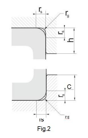
| rs Minimum | rg Maximum | h | |
| Bearing Series | |||
| 230,239, 240 | 213,231,223 241,222,233, 232 | ||
| 1 | 1 | 2,3 | 2,8 |
| 1,1 | 1 | 3 | 3,5 |
| 1,5 | 1,5 | 3,5 | 4,5 |
| 2 | 2 | 4,4 | 5,5 |
| 2,1 | 2,1 | 5,1 | 6 |
| 3 | 2,5 | 6,2 | 7 |
| 4 | 3 | 73 | 8,5 |
| 5 | 4 | 9 | 10 |
| 6 | 5 | 11,5 | 13 |
| 7,5 | 6 | 14 | 16 |
| 9,5 | 8 | 17 | 20 |
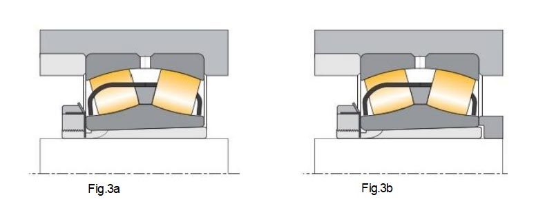
Spherical roller bearings mounted on adapter or withdrawal sleeves
For applications where spherical roller bearings and adapter sleeves are mounted on straight shafts without additional axial support,(Fig.3a), their ability to accept axial forces is limited by the
friction between the adapter sleeve and the shaft.
The permissible thrust load may be estimated using the following formula :
Famax≤3·d-B
where: Famax=maximum permissible thrust load for sphe- rical roller bearings mounted onadapterslee- ves [N]
B=bearing width [mm]
d=bearing borediameter [mm]
With higher axial forces,the bearing must be se- cured additionally by supporting rings as shown in Fig.3b.
When designing such supporting rings,however, specific dimensions have to be obtained (tables 5 and 6,next page)
Adapter sleeves: In additionto these standard sleeves which are designated H and shown in the product tables,VEO produces sleeves to other designs which differ in the number and
arrange ment of the oil ducts and distributor grooves,if it is needed extra information or in case of do- ubt,consult with the department of engineering applications VEO.
Extraction sleeves: To enable the oil injection method to be used for mounting and dismounting, VEO extraction sleeves with bore diameters of 200 mm and above are
produced as standard with oil supply ducts and distributor grooves,which are designated AOH.
These AOH sleeves have two oil supply ducts at the threaded side as well as oil distributor gro- oves in the circumferential and axial directions, both in the outside
surface and the sleeve bore.
Bearing housings
Spherical roller bearings with either cylindrical or tapered bores are frequently used in conjunction with bearing housings as complete ready to mount assemblies.
VEO also produce bearing housings for spherical roller bearings.
Mounting instructions
Particularly when mounting spherical roller bea-rings with tapered bores special care must be taken to retain a minimum residual internal bea-ring clearance after mounting.
Please request the detailed information in the dossier Handling,Mounting and Dismounting Ro-lling Bearings in case of doubt,consult with the department of engineering applications VEO.
Supplementary designations
The product tables show the standardized bea- ring configurations updated on the edition of this catalogue.These standardized configurations co- rrespond to suffix or suffixes of each bearing.
In any case,VEO can offer,under requirement, alternative designs,comprising the ones showed in the following table or many others,whose mention exceeds the purpose of the present ca-
talogue,and can be found in specific technical publications of concrete applications or series of specific bearings.
Should you need a special design not existent in these pages,please contact our Sales Department in VEO Bearings Europe.
ФАБРИКА

Торговое общение & визит


ОБЩАЯ ПРОБЛЕМА
Как сделать наши деловые отношения хорошими в долгосрочной перспективе?
1. Мы поддерживаем хорошее качество и конкурентоспособные цены, чтобы обеспечить выгоду нашим клиентам.
2. Мы относимся к каждому клиенту как к другу, независимо от того, откуда он пришел, мы искренне ведем с ним бизнес и заводим дружбу.
ПОЛУЧИТЬ БЕСПЛАТНУЮ ЦИФРУ
СВЯЗАННЫЕ ПРОДУКТЫ